Home / Insights / Servo Gain Tuning Basics: From Inertia Mismatch to Stable Response
Technical note
Servo Gain Tuning Basics: From Inertia Mismatch to Stable Response
Gain tuning on a servo drive is easier when you know which loop is actually at fault. This note separates the current, speed and position loops in the 48 V DC drive family, explains what inertia mismatch and resonance actually do to a machine, and sets out a tuning sequence that starts with the mechanics rather than with gain values. It also lists the problems that no gain setting will fix.
Three loops, three different jobs
A servo drive is not one controller, it is three nested loops, and tuning means different things at each level. On these 48 V DC drives the current loop runs at current control frequency 20 kHz, maximum 40 kHz; the speed loop runs at 10 kHz with a maximum of 20 kHz; the position loop also runs at 10 kHz with a maximum of 20 kHz. That structure is fixed by the hardware, so the first question in tuning is not which gain to set, it is which loop is the problem. If the axis will not hold position, that is a position and velocity question. If the current is noisy or the axis feels stiff at touch, that is the current loop and the mechanics behind it. Raising position gains when the real fault is a supply or an EMC problem produces a machine that oscillates instead of a diagnosis.| Loop | Control frequency | What it decides |
|---|---|---|
| Current loop | 20 kHz, maximum 40 kHz | How fast torque responds to a load change — this is the loop that governs contact behaviour |
| Speed loop | 10 kHz, maximum 20 kHz | How the axis rejects velocity disturbances |
| Position loop | 10 kHz, maximum 20 kHz | How accurately the axis follows a commanded position |
Inertia mismatch is usually the real story
Inertia mismatch is the ratio between the reflected inertia of the load and the rotor inertia of the motor. Low mismatch — a load that is light and close to the motor in terms of reflected inertia — lets you run stiff, high-bandwidth loops with little fuss. High mismatch — a large stage, a long lever arm, a heavy payload away from the axis — means the drive has to fight through it: the gains that make the near side stiff also excite the far side, and you end up with a resonance the machine has no natural answer for. As a rough industry rule of thumb, keeping the reflected load-to-rotor inertia ratio below about ten to one keeps the mechanical side inside the range where one set of gains works across position, velocity and torque modes. Above that, you are compensating for mechanics rather than tuning a drive.Resonance is not a gain problem
Resonance behaves differently from instability. If the axis hunts at a frequency you can hear, that frequency is a structural mode of your machine — the stage, the base, the cable loop, the bracket — and no gain value removes it, because you are not tuning a control loop, you are exciting a spring. The drive has a resonance suppression filter in the standard software set, and a vibration suppression filter is also available in the UF software list. Both work by attenuating energy around the offending frequency rather than by making the loop quieter. The related option worth knowing about is end-of-travel vibration suppression, which is an option rather than standard and has to be confirmed per order. I would also treat the mounting and the cable routing as part of the tuning: a stiff mount and a properly supported encoder cable remove more resonance than any filter setting.What the firmware already does for you
The firmware does more for you than older generations of drives did, and it is worth knowing what is on the toolchain before you start turning knobs. One-step auto-tuning is in the standard set: the drive identifies the response and sets the gains. Bode plot analysis is there as well, which lets you see the gain and phase margin you actually have instead of inferring it from how the machine feels. Friction compensation addresses the stick-slip and stiction you get on linear axes and in the guides of a stage. Torque ripple compensation targets the periodic error that comes from motor and encoder geometry rather than from the mechanics. Position error compensation absorbs the fixed offsets that come out of a homing procedure or a mechanical reference that is not quite the electrical zero. Short-stroke commutation detection and single-axis point-to-point control are also standard, while the electronic cam is an option. The PC application used for commissioning runs over the RS485 interface, and on the DS series you can daisy-chain commissioning between drives of the same type.A tuning sequence that survives contact with a real machine
My own sequence, on a machine that matters, runs like this. First, establish a mechanical baseline: rigid mount, supported cables, and the supply measured under load rather than at rest. Second, run the auto-tune with the intended load fitted and the intended travel limits configured — tuning an empty axis is how you end up with a machine that is unstable once the workpiece arrives. Third, look at the Bode plot and note the margin you have before you adjust anything by hand. Fourth, add friction and torque ripple compensation if the residual error is periodic, and only then touch the gains. Fifth, verify against the process requirement rather than against a feeling: repeatability over a dwell, contact force consistency, position spread across a batch. If the machine is doing force-controlled work, remember that the loop which governs the contact is the current loop.What tuning cannot fix
Some problems are not tuning problems, and it is worth being blunt about them. A collapsing DC bus, or a supply that sags under acceleration, changes the plant in a way no gain setting can compensate for. A mechanical resonance below the control bandwidth cannot be tuned out; it can only be filtered or stiffened. A loose connector, a shield problem, or an encoder cable running alongside a motor cable produces errors that look exactly like a badly tuned loop. A brake that does not release cleanly, or cogging torque larger than the holding torque at the bottom of a stroke, shows up as position error at rest. On a 48 V DC bus, regenerative behaviour matters too: braking energy has to go somewhere, and the regenerative braking channel is specified at 48 V / 28 A max with PWM output supported. If your cycle dumps a lot of energy back into the bus, talk about the supply and the braking path first.Two questions worth answering before you start
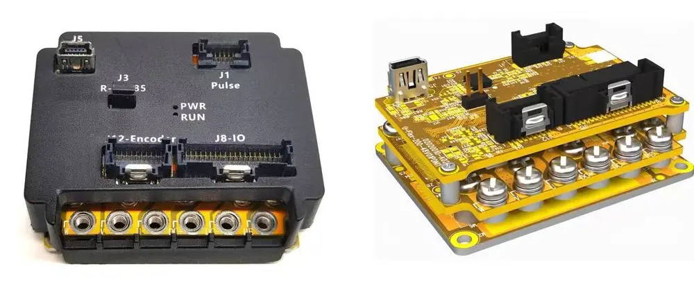
Two questions change the whole approach, so they are worth answering first: how much position error can you live with at the moment of contact, and how repeatable does the process have to be between parts. If the tolerance is tight and the process is repetitive, tuning effort belongs in rigidity, thermal behaviour and the mechanics of the homing reference — not only in the drive. If the tolerance is generous and the process varies, that effort is better spent on the sensor that measures the process variable. One more practical note for machine builders: the UF platform runs from 55 × 43 × 22.5 mm at 50.7 g on the pulse/direction version up to 70 × 50 × 33.91 mm on the EtherCAT version, so the tuning work does not change with the housing. For the parameter set and the tuning notes, the Performance Tuning application note is in the document library, and the model options are on the model parameters page.Key takeaways
- Identify which loop is at fault before touching gains: current loop 20 kHz with a maximum of 40 kHz, speed and position loops 10 kHz with a maximum of 20 kHz.
- Inertia mismatch above roughly ten to one and structural resonance are mechanical problems that filters and gains cannot solve.
- Tune with the real load fitted and verify against the process requirement, not against how the machine feels.
Common questions
What is the difference between current loop frequency and position loop frequency on these drives?
The current loop runs at 20 kHz with a maximum of 40 kHz and produces torque; the speed and position loops run at 10 kHz with a maximum of 20 kHz and command it. For force-controlled work the current loop is the one that matters, because contact force follows motor current.
Should I rely on auto-tuning?
Use it as the starting point, not the conclusion. Auto-tuning identifies the response with the axis in its current mechanical condition, so it needs the real load fitted and the travel limits configured. Then confirm the result with the Bode plot and check it against the process requirement.
My axis oscillates at one frequency and nothing else changes. What should I check?
That pattern usually points to a structural resonance rather than a control fault. Check the mount, the base, the cable loop and any bracket or guard that changed, then use the resonance suppression filter and confirm whether the mode sits above or below the control bandwidth.