Home / Insights / A four-solution map for semiconductor post-bonding
Technical note
A four-solution map for semiconductor post-bonding
Back-end bonding and packaging lines are usually described by the process step — wire bonding, die attach, inspection. Described by the axis requirement instead, the choice becomes much faster, and the options stop looking interchangeable.
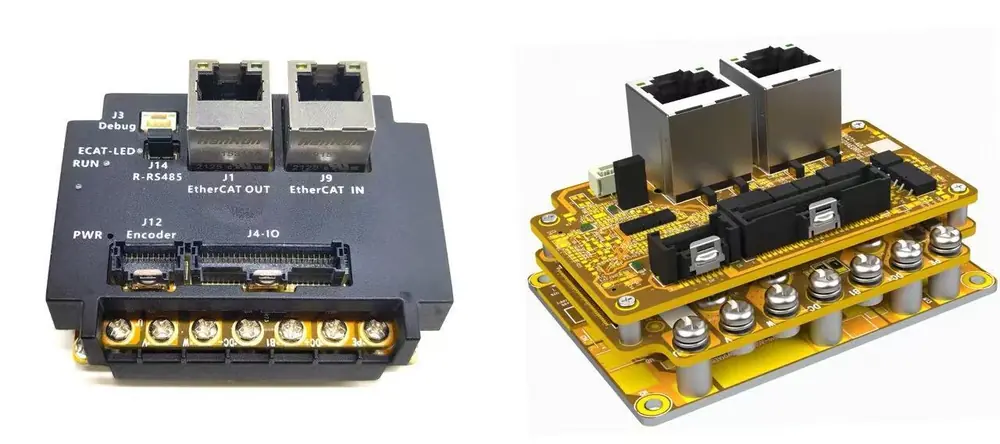
Solution 1 · Nanometre-class placement
Where the placement accuracy itself is the specification. The UF platform with the-P force variant is the relevant one here: contact force at 0.1 g resolution, current control at 20 kHz maximum 40 kHz, and 16-bit current sampling. On a die-attach stage this is the difference between a placement that is repeatable across the wafer and one that is repeatable only for the first few die.
The reasoning is straightforward. As the placement tolerance tightens, the amount of contact force you can apply without risking the die shrinks. If the drive cannot hold a small force accurately, the operator has to reduce approach speed to keep peak force down, and cycle time suffers with it.
Solution 2 · Wide-temperature handling
Post-bonding equipment often cycles between a heated stage and a cooler zone, and the cabinet is not always conditioned. The DG3 family operates from −40 to +70 °C (storage −50 to +80 °C) and accepts a dual encoder arrangement — one channel for the motor, one for the stage or tool position. Rated 24–72 VDC, 3–20 Arms, core module 55 × 46.5 × 20 mm. The dual encoder is worth pausing on. A redundant position channel lets you detect drift or a mechanical fault in the stage itself rather than inferring it from the motor encoder, which is a real diagnostic gain in a tool where a placement error is expensive to discover late.Solution 3 · Dual-axis ZR stages
Wafer handling and die attach stages are Z plus R. The dual-axis ZR drive measures 127.5 × 65 × 28.6 mm. Its force figures are worth reading carefully, because they are pressure accuracy at a 20 g target pressure rather than a contact-force figure: open-loop ±1.8 g, closed-loop ±0.5 g; rotation below 50 ms per revolution with ±0.01° repeatability, and linear motion below 80 ms per 30 mm with ±2 μm repeatability.Solution 4 · Integrated multi-axis
When the machine is a gantry or an XYZR table, the six-axis integrated unit at 165 × 120 × 18.6 mm serves the whole axis group over one EtherCAT bus instead of six separate drives and six buses. The six-axis version covers XYZR plus two, and the dual-axis ZR covers the two axes of a ZR stage. Multi-segment trajectory control is implemented in the drive, which shortens the loop and helps the axes settle faster. For a machine builder this is a wiring and cabinet decision before it is a performance decision: one bus, one connector set, fewer parts to specify.Choosing between them
One practical note on multi-axis selection that is not in most comparison charts: the mainstream multi-axis product in this range is the G-series six-axis unit, not the DM family. DM tops out at four axes and is limited to −10 to +45 °C, which is not enough for a tool that runs warm.| If your constraint is… | Look at… |
|---|---|
| Placement accuracy in nanometres | UF with the -P force variant |
| Temperature cycling, vibration, or a redundant position channel | DG3 wide-temperature dual-encoder |
| A Z plus R stage | Dual-axis ZR drive |
| A gantry or an XYZR table | Six-axis integrated unit |
Key takeaways
- Describe the machine by its axis requirement, not its process name — the four architectures map cleanly once you do.
- ZR pressure accuracy (±0.5 g closed-loop at a 20 g target) and UF contact force (~10 g ±1 g) are different measurements and should not share a table column.
- For multi-axis machines the G-series six-axis unit is the mainstream choice; DM is limited to four axes and −10 to +45 °C.
Common questions
Which solution suits a die attach stage that runs warm near a heated chuck?
Temperature is usually the deciding constraint, and it points to the DG3 wide-temperature family at −40 to +70 °C rather than the UF platform, whose operating range is 0 to +45 °C. If you also want a redundant position channel, the DG3 dual encoder arrangement covers that as well.
Do I need force control for a bonding stage, or is positioning enough?
For die attach, yes. The process window between not touching and cracking the die is narrow enough that position accuracy alone does not protect the part — the tool has to know how hard it pressed. For inspection or metrology stages that never contact the wafer, force control is not needed and you should judge the drive on positioning behaviour instead.
Is the six-axis integrated unit worth it for a four-axis gantry?
Often yes, because it consolidates the axis group onto one bus and reduces cabinet complexity, but it is a wiring and cost decision rather than a performance one. If your gantry is genuinely four axes and the cabinet is already built around individual drives, separate drives remain a reasonable answer. Send me the axis list and the cycle time and I will give you a straight recommendation.