Home / Insights / Why a 48 V DC architecture changes how force control behaves
Technical note
Why a 48 V DC architecture changes how force control behaves
If your machine has to touch something and not damage it, the question you are really asking is not "how much force" but "how fast does the force loop react, and how repeatable is it across a batch". Both of those are decided by the current loop, not by the force number on the datasheet.
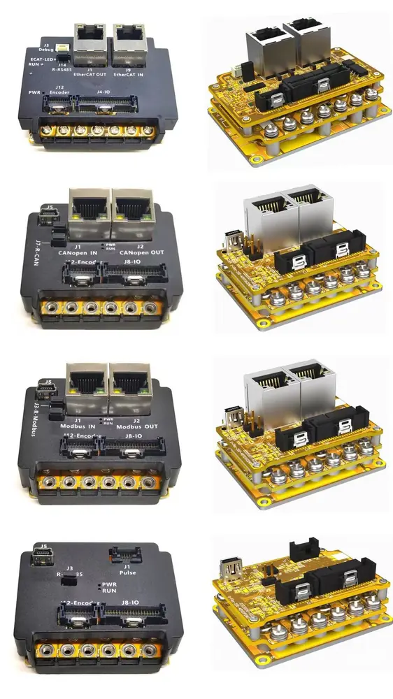
Force control is a current-control problem
Torque is proportional to motor current. If you can measure and regulate current tightly, you can regulate force — the mechanical side of the machine does the rest. So the quality of the force loop is decided by how fast and how cleanly the drive regulates current, not by how the force setpoint is expressed in the software. On these drives the current control frequency is 20 kHz, maximum 40 kHz, with 12-bit current sampling, and 16-bit sampling on the-P variant. That is the number that determines how quickly a force setpoint can be corrected when the workpiece changes — a thicker die, a slightly different pad height, a part that is slightly off nominal. Every millisecond the loop takes to notice and correct is a millisecond of extra contact force on the part.
Why the bus architecture matters
There are two ways to build soft landing into a machine. The first is to put a force sensor between the tool and the workpiece and close a loop around it. That works, and it is a legitimate engineering choice — but it introduces a part that has to be mounted, calibrated, cabled and eventually replaced when it wears, and it adds a failure mode to a machine whose only job is to be gentle. The second is to derive force from the motor current the drive is already regulating on a 48 V DC bus. The sensing lives inside the drive, and the force signal inherits the current loop's bandwidth rather than a sensor's bandwidth and filtering. The trade-off is real and worth stating plainly: because the sensing is inside the drive, it needs the right firmware configuration and it is tied to the drive's current-loop performance rather than to a separate sensor's calibration. If your process needs certified traceable force measurement for compliance, that is a different requirement and a force sensor may well be the right answer.The figures, and what each one means
| Item | Value | Note |
|---|---|---|
| Contact force | typically around 10 g, roughly ±1 g variation | Higher-performance -P variant: 0.1 g resolution |
| Current control frequency | 20 kHz, maximum 40 kHz | Sets how fast a force setpoint can be corrected |
| Speed / position control frequency | 10 kHz, maximum 20 kHz | |
| Current sampling | 12-bit standard, 16-bit on -P | Resolution available on the force-control version |
| Multi-segment trajectory control | standard across the range | Implemented inside the drive |
What “implemented inside the drive” actually buys you
Multi-segment trajectory control is a firmware function, not a separate motion controller. Because it runs in the drive, the control loop from command to output is shorter than in a drive-plus-external-controller arrangement. Shorter loop, faster response, faster settling. This is worth being precise about, because it is easy to misread as a claim that one board replaces a controller. It does not. If your machine genuinely needs a separate motion controller — for multi-axis interpolation, for a machine PLC, for anything your safety logic depends on — you still need one. What changes is how tightly the motion and the drive can be coordinated inside each axis, and how much of the trajectory handling you have to build yourself.How this shows up on the bench
The practical test I would run with any candidate drive is not to compare force numbers on a datasheet but to put your own workpiece under it. Load the target, command the approach, and look at what the force signal actually does at the moment of contact. A drive with a fast current loop settles quickly and predictably; a drive with a slower one rings, overshoots, or creeps. The force control application note in the documents library describes the configuration, which is the fastest way for your own engineer to check the behaviour on your part rather than take a figure on trust. If you would rather walk through it with your specific material, send me the setup.Key takeaways
- Force control quality is set by the current loop, so compare current-loop frequency and sampling resolution — not force figures.
- Deriving force from regulated motor current keeps the sensing inside the drive; it does not remove the trade-off of needing correct firmware configuration.
- Multi-segment trajectory control moving into the drive shortens the loop and speeds settling, but it is function integration, not a replacement for an external motion controller.
Common questions
Does the 48 V DC architecture mean the drive can produce any force it is told to?
No. The drive regulates current within the limits of the motor and the supply. The architecture determines how quickly and how precisely the commanded current is reached and held, which is what determines contact-force repeatability. The achievable force still depends on motor torque constant, gear ratio and supply voltage.
If force comes from motor current, do I still need a force sensor?
For force-limited contact processes you generally do not need one, because the drive already measures the current that produces the force. For traceable or certified force measurement required by a compliance regime, a force sensor remains the appropriate instrument. It is worth deciding which requirement you actually have before choosing.
How much does multi-segment trajectory control shorten the control loop?
It removes the trajectory-processing step from the external controller and runs it in the drive firmware, so the path from a command to a current output is shorter. The practical effect is faster settling and tighter repeatability between segments. The exact improvement depends on the axis mechanics and is something to measure on the machine.