Home / Insights / EtherCAT Cycle Time in Servo Drives: 4 kHz vs 40 kHz and Why It Matters
Technical note
EtherCAT Cycle Time in Servo Drives: 4 kHz vs 40 kHz and Why It Matters
Two numbers in the same datasheet get compared constantly: a 4 kHz EtherCAT real-time cycle and a current control frequency of 20 kHz with a maximum of 40 kHz. They describe different layers of the system, and treating them as competitors leads to wrong conclusions about speed, synchronisation and control performance. This note separates them, shows what each one governs in a real machine, and sets out how to choose and then verify a cycle time on the master side.
Two numbers, two different layers
The comparison between a 4 kHz EtherCAT bus cycle and a current control frequency of 20 kHz with a maximum of 40 kHz comes up because two figures in the same document get read as if they describe the same thing. They do not. 4 kHz is the EtherCAT real-time cycle — how often the master exchanges process data with the drive. The current control frequency is 20 kHz, with a maximum of 40 kHz — that is how fast the current loop runs inside the drive. The first is a property of the network and the master. The second is a property of the drive's hardware and firmware, and it never waits for the bus. Confusing them produces two opposite errors: buying a fast drive and expecting the bus to deliver fast setpoints, or buying a slow bus and assuming the motor control is slow with it.The numbers and what each one governs
The table below separates the four frequencies that appear in the documentation, because mixing them up is the usual root of a disappointing machine.| Parameter | What it governs | Value |
|---|---|---|
| EtherCAT real-time cycle | Master-to-drive process data exchange; D, DS, UF, DR and the multi-axis units | ≤ 4 kHz |
| EtherCAT real-time cycle | The DG3 wide-temperature variant, which runs a slower bus | ≤ 2 kHz |
| Current control frequency | The inner torque-producing loop inside the drive | 20 kHz, maximum 40 kHz |
| Speed control frequency | The velocity loop inside the drive | 10 kHz, maximum 20 kHz |
| Position control frequency | The position loop inside the drive | 10 kHz, maximum 20 kHz |
What the bus cycle actually does for you
What the bus cycle governs is how quickly a new target reaches the drive, and how quickly actual position comes back to the master. With a 4 kHz cycle you have a 250 µs exchange interval before you add the latency of the master, the cable and the drive's own input processing. For a gantry or an XYZR table that has to move in synchronised steps, that interval sets the floor on how finely the master can interleave commands across axes. It is also the number that decides how many axes you can keep genuinely coordinated on one bus: each axis consumes part of the same cycle budget, and the controller has to complete its own processing for all of them inside that window. What the cycle time does not define is how precisely an axis holds position between exchanges — the drive closes its own loops continuously, regardless of when the master last spoke to it.Why the current loop does not wait for the bus
The reason the internal loops are faster than the bus is the whole point of a decentralised drive architecture, so it is worth stating plainly. The current loop measures the motor current and corrects it tens of thousands of times per second. If the bus stopped delivering data entirely, the drive would still regulate current, still hold its position loop against a disturbance, and still follow the last target it was given. What it would stop doing is accepting new targets. So a 4 kHz bus on a drive whose current loop runs at 20 kHz, with a maximum of 40 kHz, is not a slow system; it is a system whose command interface is deliberately slower than its motor control. For disturbance rejection, contact-force response and stiffness against load, the number to look at is the current loop, because that is the loop that turns a current into torque without waiting for the bus. For motion rate and multi-axis coordination, the number is the bus cycle. Asking which one is better is asking which part of the machine you are worried about.Multi-axis and synchronisation
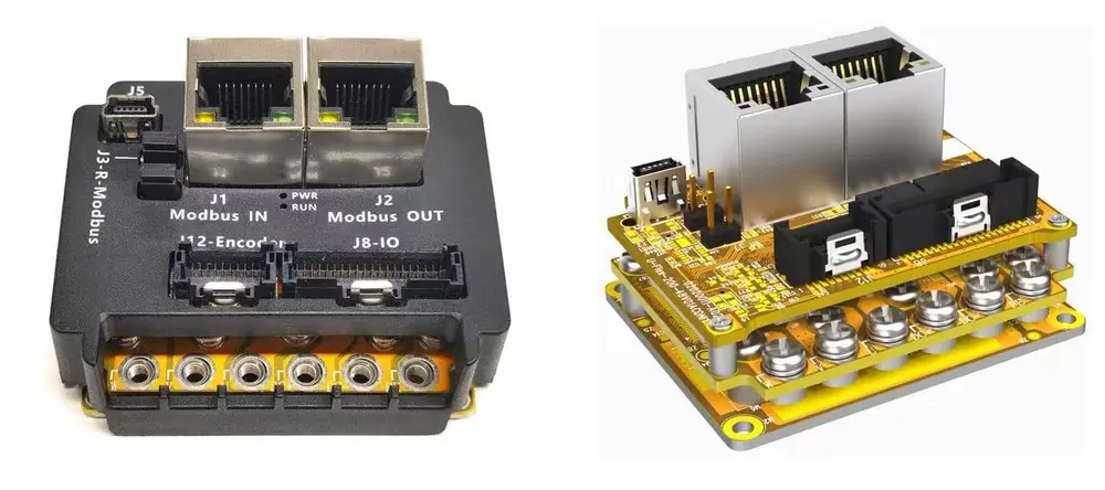
On multi-axis machines the cycle time becomes a coordination problem rather than a speed problem. The G series six-axis EtherCAT unit,GM1-E48xxN-6D-MT6, serves the whole axis group over one bus instead of six separate buses, which keeps the master's job to one bus and one set of cycle settings. The dual-axis ZR unit, GM1-E48xxN-2D-ZR, does the same for the two axes of a ZR stage. When axes are chained, the master's cycle time has to be short enough to hold the group's synchronisation error inside what the process tolerates, and a shared bus means that adding axes costs cycle budget on every axis. That is the calculation to do before deciding how many axes belong on one unit. Two honest notes on the G family while we are here: the multi-axis units carry minimal I/O per axis — one digital input, two digital outputs and one analogue input on the six-axis unit — and STO is not part of the G family at all, so a machine built on these modules needs its safety function handled elsewhere.
Choosing a cycle time for your throughput
Choosing a cycle time is a throughput-versus-latency decision, and it is worth stating the requirement rather than accepting a default. If the machine spends most of its cycle in long dwells — loading, bonding, curing, inspection — then the bus cycle is not the constraint and the process time dominates the takt. If the machine is dominated by short, repeated moves, then command latency and the master's ability to issue the next move quickly matter more, and you want the shortest practical cycle with jitter you can characterise. What matters most in practice is not the nominal cycle but the deviation from it: a bus that nominally runs at 4 kHz and occasionally stalls is worse for synchronisation than a stable, slightly slower one. So specify the required cycle, the required synchronisation accuracy and the number of axes, then ask the master vendor for the distributed clock behaviour and the worst-case jitter it can hold with your axis count.Master-side checks worth doing
A few things on the master side decide whether the drive performs as well as its datasheet suggests, and they are worth checking rather than assuming. Confirm the master's distributed clocks are enabled and that it reports the actual cycle rather than the configured one. Check the DC jitter and the synchronisation error under load, with all axes enabled and the machine moving, because an idle bus is a quiet bus. Verify that the drive's task assignment matches your cycle time — a drive assigned to a slower task than the bus behaves as though it were slower, and this is a common and confusing symptom. On the drive side, the EtherCAT settings and master adaptation documents are in the document library, and the bus options with their cycle figures are listed against the models on the model parameters page. For non-EtherCAT architectures the same logic applies with different numbers: CANopen runs at up to 1 Mbps, Modbus over RS485 up to 1 Mbps, and pulse/direction replaces message exchange with a hardware signal train. Different mechanism, same question about how fresh the command is.Key takeaways
- 4 kHz is the EtherCAT process data cycle; 20 kHz with a maximum of 40 kHz is the internal current control frequency. They govern different layers and are not comparable.
- Bus cycle time sets command latency and multi-axis coordination budget; the current loop governs disturbance rejection, stiffness and contact response.
- Verify the actual cycle and worst-case jitter on the master under load, and check that each drive's task assignment matches the cycle you configured.
Common questions
What is the EtherCAT cycle time on these drives?
The EtherCAT real-time cycle is specified as ≤ 4 kHz on the D, DS, UF, DR and the multi-axis EtherCAT products; the DG3 wide-temperature variant is specified at ≤ 2 kHz. That is the process data exchange interval between master and drive — it is not the drive's internal control frequency.
Is a 4 kHz bus cycle slow compared with the current loop?
They describe different things, so there is nothing to compare. The current loop runs inside the drive at 20 kHz, with a maximum of 40 kHz, and keeps controlling torque between bus exchanges. The 4 kHz cycle sets how often new targets and new positions travel over the bus.
How many axes can I run on one EtherCAT bus?
The G series six-axis EtherCAT unit runs six axes over one bus and the dual-axis ZR unit runs the two axes of a ZR stage, with ID addresses mapped by fixed configuration. Whether they stay synchronised within your tolerance depends on the master cycle and its jitter under load, which is worth verifying with the master vendor before the build.