Home / Applications / Semiconductor die attach with 48 V DC servo drives
Technical note
Semiconductor die attach with 48 V DC servo drives
Force control is the whole point here. The die is fragile, the bond line is thin, and the process window between “not touching” and “cracking” is measured in grams.
What the motion looks like
A four-stage motion profile: rapid approach over the long distance, a slow approach close to the die, contact at a defined force, and a controlled dwell before release. The fast stage sets takt time; the slow stage sets yield. Everything interesting happens in the last two.Does it need force control?
Contact force is the controlling variable, not a side effect. The die is bonded onto a substrate or onto a heated chuck, and both the bond line thickness and the die's own fracture strength define how much force is acceptable. The process window is narrow and it moves with every lot.What to look at in the specification
| Requirement | What it implies for the drive |
|---|---|
| Force resolution at the bond line | 0.1 g resolution → the high-performance -P variant with 16-bit current sampling |
| Force repeatability across a wafer | Current loop speed: 20 kHz, maximum 40 kHz |
| Position accuracy of the placement | ZR stages: rotational ±0.01°, linear ±2 μm repeatability |
| Stable stage position under thermal load | DG3 wide-temperature dual encoder if the tool runs warm |
| Coordinated Z + R motion | Dual-axis ZR drive, or G-series six-axis for a gantry |
A selection checklist you can send to your engineer
Send this list to whoever is doing the mechanical work. If the answers come back with specific numbers rather than adjectives, the drive selection is half done — and so is the quotation.- Force resolution at the bond line
0.1 g resolution → the high-performance -P variant with 16-bit current sampling - Force repeatability across a wafer
Current loop speed: 20 kHz, maximum 40 kHz - Position accuracy of the placement
ZR stages: rotational ±0.01°, linear ±2 μm repeatability - Stable stage position under thermal load
DG3 wide-temperature dual encoder if the tool runs warm - Coordinated Z + R motion
Dual-axis ZR drive, or G-series six-axis for a gantry
Common mistakes I see
- Applying a position setpoint that drives the tool into the die and hoping the resulting current draw is a force measurement. It is not — it is a force symptom, arriving late and at whatever magnitude the mechanics produced.
- Assuming the bond line needs the same force everywhere on the wafer. Thermal expansion and pad height variation mean the contact point moves, so the force setpoint has to be re-established per die, which is exactly what a fast force loop buys you.
- Using a wide-temperature drive in a hot tool and expecting the force figure to hold. The
-Pforce resolution and the −40 to +70 °C range are different product attributes; check both.
Cycle time and settling
On cycle time, the number that usually matters is not the drive's speed rating but the deceleration distance. Most soft-landing implementations use a two-stage profile: a fast traverse at up to a couple of hundred mm/s, then a controlled approach at a speed proportional to the remaining distance. The slow stage exists to bound the peak contact force, and its speed sets the cycle contribution. If the takt time is tight, the lever is usually the fast traverse and the deceleration distance, not the contact phase — the contact phase should stay slow whatever the takt target. The second lever is settling. A multi-segment trajectory profile in the drive shortens the loop between command and output, which means the axis reaches its final position sooner and the next die can start. That is where a lot of the throughput gain in a die attach tool actually comes from — not from a faster approach speed, but from less dead time while the axis settles.Where I would start
Starting point: UF with the -P force variant, or DG3 -P if the tool runs hot.. That is a starting point, not a finished selection — the deciding inputs are the motor model, the bus interface, the payload or stroke, the axis count and the ambient temperature. The parameter reference lists what each family covers, and the documents library has the cable tables and application notes your engineer will want.Key takeaways
- Where I would start: UF with the -P force variant, or DG3 -P if the tool runs hot.
- Compare the current-loop and sampling specifications, not the force headline — the force number alone does not decide these applications.
- If the axis never touches the workpiece, say so. Position-control criteria are the right ones to judge on.
- Send the checklist to your mechanical engineer before choosing a model — most wrong selections start as an incomplete brief.
Common questions
Is a 48 V DC servo drive the right choice for semiconductor die attach?
It depends on whether the axis makes contact and on the thermal environment. My starting recommendation for semiconductor die attach is UF with the -P force variant, or DG3 -P if the tool runs hot. — but the motor model, payload, bus type and ambient decide it properly. Send me those four and I will give you a specific answer.
Do I need force control for this application?
Contact force is the controlling variable, not a side effect. The die is bonded onto a substrate or onto a heated chuck, and both the bond line thickness and the die's own fracture strength define how much force is acceptable. The process window is narrow and it moves with every lot.
Can one drive cover several axes in this machine?
For synchronised axes on one bus, the G-series multi-axis units cover pairs and six-axis groups over EtherCAT. If the axes are independent, separate drives are usually simpler and cheaper. Tell me the axis count and which axes must move together.
Which communication interface should I specify?
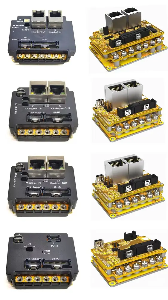
EtherCAT if you have multiple axes that must move together, or if you need STO. Modbus-RTU or CANopen for simple point-to-point axes where the motion is self-contained. Pulse/direction when you are retrofitting into an existing controller. One warning worth repeating: STO exists on EtherCAT models only, so if your safety case needs it, that decision forces the bus choice.
How do I validate the choice before committing to a quantity?
Run the drive on your own part, not on a test piece. The ForceControl Application note in the documents library describes the setup, and the current-loop and sampling figures in the parameter reference tell you what to look for in the force signal at the moment of contact. If you would rather have someone look at your data with you, send me the traces.