Home / Applications / IVD and laboratory pipetting with 48 V DC servo drives
Technical note
IVD and laboratory pipetting with 48 V DC servo drives
Low mass, low inertia, repeatable contact force — and a hard limit on how much force you apply to a fragile well.
What the motion looks like
Small strokes, low mass, and a hard requirement that the tip touch the well without pressing hard enough to damage it. The whole axis is small, which means the mechanics are light and the drive has very little inertia to work with.Does it need force control?
Contact force here is a limit rather than a target. The system needs to know the tip has reached the well and that the downward force has not exceeded a threshold — the tip, the well and the liquid all have tolerances.What to look at in the specification
| Characteristic | What to look for |
|---|---|
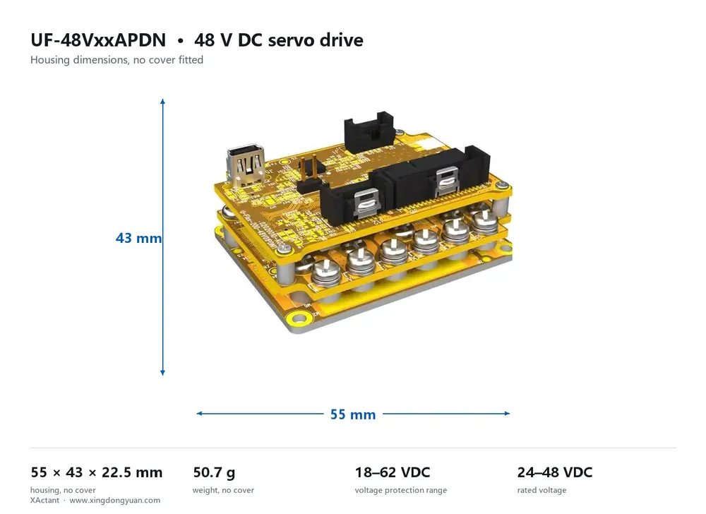
| Axis size and mass | Compact drive; UF-…-AP measures 55 × 43 × 22.5 mm at 50.7 g |
| Force limit resolution | 0.1 g on the -P variant |
| Noise | Direct-current bus and no brake chatter — relevant next to a lab analyser |
| Interface | Modbus or pulse/direction is typical for instrument builders |
A selection checklist you can send to your engineer
Send this list to whoever is doing the mechanical work. If the answers come back with specific numbers rather than adjectives, the drive selection is half done — and so is the quotation.- Axis size and mass
Compact drive; UF-…-AP measures 55 × 43 × 22.5 mm at 50.7 g - Force limit resolution
0.1 g on the -P variant - Noise
Direct-current bus and no brake chatter — relevant next to a lab analyser - Interface
Modbus or pulse/direction is typical for instrument builders
Common mistakes I see
- Over-pressing a well that is designed to be touched, not compressed. Lab consumables vary more than production parts do, so the force limit has to be a soft ceiling, not a setpoint you push toward.
- Forgetting that IVD instruments often run at a different ambient than the production floor. Confirm the drive's operating range against the instrument enclosure temperature, not the room.
Cycle time and settling
Cycle time in a pipetting head is dominated by the Z move and the dwell, not by the drive's specification. A compact axis with low moving mass settles faster, and because the tip has to be positioned relative to a well rather than pressed into it, the positional repeatability is what sets the miss rate. One practical consequence of the small scale: the current ratings involved are small, which means the drive's own footprint matters. A 55 × 43 × 22.5 mm and 50.7 g version of the UF platform exists specifically for packaging headroom, and in an instrument with four or six tips around the same plate, that space is worth more than it sounds.Where I would start
Starting point: UF -P in the compact AP mechanical version, or a compact DG variant if the enclosure runs warm.. That is a starting point, not a finished selection — the deciding inputs are the motor model, the bus interface, the payload or stroke, the axis count and the ambient temperature. The parameter reference lists what each family covers, and the documents library has the cable tables and application notes your engineer will want.Key takeaways
- Where I would start: UF -P in the compact AP mechanical version, or a compact DG variant if the enclosure runs warm.
- Compare the current-loop and sampling specifications, not the force headline — the force number alone does not decide these applications.
- If the axis never touches the workpiece, say so. Position-control criteria are the right ones to judge on.
- Send the checklist to your mechanical engineer before choosing a model — most wrong selections start as an incomplete brief.
Common questions
Is a 48 V DC servo drive the right choice for ivd and laboratory pipetting?
It depends on whether the axis makes contact and on the thermal environment. My starting recommendation for ivd and laboratory pipetting is UF -P in the compact AP mechanical version, or a compact DG variant if the enclosure runs warm. — but the motor model, payload, bus type and ambient decide it properly. Send me those four and I will give you a specific answer.
Do I need force control for this application?
Contact force here is a limit rather than a target. The system needs to know the tip has reached the well and that the downward force has not exceeded a threshold — the tip, the well and the liquid all have tolerances.
Can one drive cover several axes in this machine?
For synchronised axes on one bus, the G-series multi-axis units cover pairs and six-axis groups over EtherCAT. If the axes are independent, separate drives are usually simpler and cheaper. Tell me the axis count and which axes must move together.
Which communication interface should I specify?
EtherCAT if you have multiple axes that must move together, or if you need STO. Modbus-RTU or CANopen for simple point-to-point axes where the motion is self-contained. Pulse/direction when you are retrofitting into an existing controller. One warning worth repeating: STO exists on EtherCAT models only, so if your safety case needs it, that decision forces the bus choice.
How do I validate the choice before committing to a quantity?
Run the drive on your own part, not on a test piece. The ForceControl Application note in the documents library describes the setup, and the current-loop and sampling figures in the parameter reference tell you what to look for in the force signal at the moment of contact. If you would rather have someone look at your data with you, send me the traces.